Saturday, June 13, 2015

Zero Power Factor ( ZPF) method: Potier Triangle Method For Alternator

Regulation by Zero Power Factor ( ZPF) method:

During the operation of the alternator, resistance voltage drop IaRand armature leakage reactance drop IaXL are actually emf quantities and the armature reaction reactance is a mmf quantity. To determine the regulation of the alternator by this method OCC, SCC and ZPF test details and characteristics are required.

-As explained earlier OC and SC tests are conducted and OCC and SCC are drawn.
-ZPF test is conducted by connecting the alternator to ZPF load and exciting the alternator in such way that the alternator supplies the rated current at rated voltage running at rated speed.
-To plot ZPF characteristics only two points are required. One point is corresponding to the zero voltage and rated current that can be obtained from scc and the other at rated voltage and rated current under zpf load.
-This zero power factor curve appears like OCC but shifted by a factor IXL vertically and horizontally by armature reaction mmf as shown below in figure. 


Following are the steps to draw ZPF characteristics:

-By suitable tests plot OCC and SCC. Draw air gap line. Conduct ZPF test at full load for rated voltage and fix the point B.

-Draw the line BH with length equal to field current required to produce full load
current on short circuit..
-Draw HD parallel to the air gap line so as to cut the OCC. Draw DE perpendicular to HB or parallel to voltage axis.
-Now, DE represents voltage drop IXL and BE represents the field current required to overcome the effect of armature reaction.
-Triangle BDE is called Potier triangle and XL is the Potier reactance. Find E from V, IRa, IXL and .
-Use the expression E =√ (V cos  Ø+ IRa)² + (V sin ) + IXL)² to compute E. Find field current corresponding to E. Draw FG with magnitude equal to BE at angle (90+ ) from field current axis, where is the phase angle of current from voltage vector E (internal phase angle).
-The resultant field current is given by OG. Mark this length on field current axis. From OCC find the corresponding E0. Find the regulation.

Share:

Thursday, June 11, 2015

MMF method:Voltage Regulation of Alternator By MMF method

Voltage Regulation of Synchronous Generator  By MMF method:-

This method is also known as amp - turns method. In this method the all the emfs produced by rotor and stator are replaced by their equivalent MMFs (fluxes), and hence called mmf method

In this method also it is assumed that the magnetic circuit is unsaturated. In this method both the reactance drops are replaced by their equivalent mmfs. Figure shows the complete phasor diagram for the mmf method. Similar to emf method OC and SC characteristics are used for the determination of regulation by mmf method. Using the details it is possible determine the regulation at different power factors.

From the phasor diagram it can be seen that the mmf required to produce the emf E1= ( V + IRa) is FR1.In large machines resistance drop may neglected.
The mmf required to over come the reactance drops is (A+Ax) as shown in phasor diagram. The mmf (A+Ax) can be found from SC characteristic as under SC condition both reactance drops will be present.

Following procedure can be used for determination of regulation by mmf method.
(i) By conducting OC and SC test plot OCC and SCC as shown in figure 2.
(ii) From the OCC find the field current If1 required to produce the voltage, E1= ( V + IRa).
(iii) From SCC find the magnitude of field current If2=( A+Ax) to produce the required armature current. A+Ax can also found from ZPF characteristics.
(iv) Draw If2 at angle (90+Ø ) from If1, where Ø  is the phase angle of current w. r. t voltage. If
current is leading, take the angle of If2 as (90- Ø ) as shown in figure 36.
(v) Determine the resultant field current, If and mark its magnitude on the field current axis.
(vi) From OCC. find the voltage corresponding to If, which will be E0 and hence find the regulation.

**Click On The Image To Get Clear View If any problem comment below

Note : In most of the cases as number of turns on the field winding is not known, the m.m.f. is calculate and expressed i terms of the field current itself.

Because of the assumption of unsaturated magnetic circuit the regulation computed by this method will be less than the actual and hence this method of regulation is called optimistic method.

Another Derivation For MMF Method:-


Theory is same as above

The two components of total field m.m.f. which are FO and FAR are indicated in O.C.C. (open circuit characteristics) and S.C.C. (short circuit characteristics) as shown in the Figure.


Zero lagging p.f. : As long as power factor is zero lagging, the armature reaction is completely demagnetising. Hence the resultant FR is the algebraic sum of the two components FO and FAR. Field m.m.f. is not only required to produce rated terminal voltage but also required to overcome completely demagnetising armature reaction effect.


       This is shown in the Fig
       OA = FO
       AB = FAR   demagnetising
       OB = FR = FO + FAR
       Total field m.m.f. is greater than FO.

Zero leading p.f. : When the power factor is zero leading then the armature reaction is totally magnetizing and helps main flux to induce rated terminal voltage. Hence net field m.m.f. required is less than that required to induce rated voltage normally, as part of its function is done by magnetising armature reaction component. The net field m.m.f. is the algebraic difference between the two components FO and FAR. 

This is shown in the Fig.
OA = FO
       AB = FAR magnetising
       OB = FO - FAR = FR
       Total m.m.f. is less than FO.

Unity p.f. : Under unity power factor condition, the armature reaction is cross magnetizing and its effect is to distort the main flux. Thus and F are at right angles to each other and hence resultant m.m.f. is the vector sum of FO and FAR.

OA = FO 
       AB = FAR cross magnetising
OB=FR=FO=FAR.


Generalized Formula:-


(FR)²= (FO)² + ( FAR)²-2(FO)( FAR)Cos(FO^FAR)

FO^FAR =90-Φ if Φ leading
          =90+Φ if Φ is lagging

Regulation :-
%R=Eph-Vph/Vph *100


Share:

[*EASY*] Voltage Regulation of Synchronous Generator [Alternator] By EMF Method or Synchronous Impedance Method

Voltage Regulation of Synchronous Generator [Alternator] By EMF Method or Synchronous Impedance Method

EMF method: This method is also known as synchronous impedance method.Here the magnetic circuit is assumed to be unsaturated. In this method the MMFs (fluxes) produced by rotor and stator are replaced by their equivalent emf, and hence called emf method.To predetermine the regulation by this method the following information is to be determined.Armature resistance/phase of the alternator, open circuit and short circuit characteristics of the alternator.

Here we discussed Voltage Regulation of Synchronous Generator [Alternator] by EMF Method or Synchronous Impedance Method.this is better method than direct loading but not best methods to find out voltage regulation.

Synchronous Impedance Method:

To perform  voltage regulation by emf method we need to calculate the following data.

1.Armature Resistance per phase [Ra]

2.Open Circuit characteristics which is a graph between open circuit voltage [Vo.c.] and field current.

3.Short circuit characteristics which is a graph between short circuit current [Is.c.] and field current.

Voltage Regulation Synchronous Generator by Synchronous Impedance Method

In Synchronous Impedance Method we need to calculate OC and SC characteristics to find Synchronous Impedance.so..follow these steps to find out OC & SC test values.

Open Circuit Characteristic (O.C.C.):-


The open-circuit characteristic or magnetization curve is really the B-H curve of the complete magnetic circuit of the alternator. Indeed, in large turboalternators, where the air gap is relatively long, the curve shows a gradual bend. It is determined by inserting resistance in the field circuit and measuring corresponding value of terminal voltage and field current. Two voltmeters are connected across the armature terminals. The machine is run at rated speed and field current is increased gradually to If1 till armature voltage reaches rated value or even 25% more than the rated voltage. Figure illustrates a typical circuit for OC test.The major portion of the exciting ampere-turns is required to force the flux across the air gap, the reluctance of which is assumed to be constant. A straight line called the air gap line can therefore be drawn as shown, dividing the excitation for any voltage into two portions,

 (a) that required to force the flux across the air gap, and
 (b) that required to force it through the remainder of the magnetic circuit.
The shorter the air gap, the steeper is the air gap line.


Procedure to conduct OC test:
(i) Start the prime mover and adjust the speed to the synchronous speed of the alternator.
(ii) Keep the field circuit rheostat in cut in position and switch on DC supply.
(iii) Keep the TPST switch of the stator circuit in open position.
(iv) Vary the field current from minimum in steps and take the readings of field current and
stator terminal voltage, till the voltage read by the voltmeter reaches up to 110% of rated voltage. Reduce the field current and stop the machine.
(v) Plot of terminal voltage/ phase vs field current gives the OC curve.


Short Circuit Characteristic (S.C.C.):-

The short-circuit characteristic, as its name implies, refers to the behaviour of the alternator when its armature is short-circuited. In a single-phase machine the armature terminals are short-circuited through an ammeter, but in a three phase machine all three phases must be short-circuited. An ammeter is connected in series with each armature terminal, the three remaining ammeter terminals being short-circuited. 

The machine is run at rated speed and field current is increased gradually to If2 till armature current reaches rated value. The armature short-circuit current and the field current are found to be proportional to each other over a wide range, as shown in Figure, so that the short circuit characteristic is a straight line. Under short-circuit conditions the armature current is almost 90° out of phase with the voltage, and the armature mmf has a direct demagnetizing action on the field.The resultant ampere − turns inducing the armature emf are, therefore, very small and is equal to the difference between the field and the armature ampere − turns. 

This results in low mmf in the magnetic circuit, which remains in unsaturated condition and hence the small value of induced emf increases linearly with field current. This small induced armature emf is equal to the voltage drop in the winding itself, since the terminal voltage is zero by assumption. It is the voltage required to circulate the short circuit current through the armature windings. The armature resistance is usually small compared with the reactance.

Short-Circuit Ratio:
The short-circuit ratio is defined as the ratio of the field current required to produce rated volts on open circuit to field current required to circulate full-load current with the armature short-circuited.

Short-circuit ratio = If1/If2

Determination of synchronous impedance Zs:

As the terminals of the stator are short circuited in SC test, the short circuit current is circulated against the impedance of the stator called the synchronous impedance. This impedance can be estimated form the oc and sc characteristics.The ratio of open circuit voltage to the short circuit current at a particular field current, or at a field current responsible for circulating the rated current is called the synchronous impedance.

synchronous impedance Zs = (open circuit voltage per phase)/(short circuit current per phase)
for same If
Hence Zs = (Voc) / (Isc)
for same If
From figure synchronous impedance Zs = V/Isc

Armature resistance Ra of the stator can be measured using Voltmeter Ammeter method. Using synchronous impedance and armature resistance synchronous reactance and hence regulation can be calculated as follows using emf method.

Zs =(Ra)² + (XS)² and Synchronous reactance Xs =  ( Zs)² - (Ra)²

Hence induced emf per phase can be found as 
Eph = √ [ (V cos  Ø+ IRa)²+ (V sin  Ø ± IXS)²]
where
V = phase voltage per phase = Vph ,
I = load current per phase
in the above expression in second term + sign is for lagging power factor and
– sign is for leading power factor.

% Regulation = [(Eph – Vph / Vph )] x 100

where Eph = induced emf /phase, Vph = rated terminal voltage/phase.


Synchronous impedance method is easy but it will not give accurate results. This method gives the value of regulation which is greater (poor) than the actual value and hence this method is called pessimistic method. The complete phasor diagram for the emf method is shown in above figure.


Tags: Synchronous generator voltage regulation,voltage regulation of a synchronous machine by EMF Method or Synchronous Impedance Method,voltage regulation in alternators.Synchronous Impedance Method pdf,Synchronous Impedance Method ppt.
Share:

Voltage Regulation:Synchronous Generator or Alternator

Voltage regulation of an alternator :

When an alternator is subjected to a varying load, the voltage at the armature terminals varies to a certain extent, and the amount of this variation determines the regulation of the machine. When the alternator is loaded the terminal voltage decreases as the drops in the machine stars increasing and hence it will always be different than the induced emf.

Voltage regulation of an alternator is defined as the change in terminal voltage from no load to full load expressed as a percentage of rated voltage when the load at a given power factor is removed with out change in speed and excitation. Or The numerical value of the regulation is defined as the percentage rise in voltage when full load at the specified power-factor is switched off with speed and field current remaining unchanged expressed as a percentage of rated voltage.

**This definition of voltage regulation can be applied for any electrical  machine.


Hence regulation can be expressed as


% Regulation = (Eph – Vph / Vph ) x 100

where Eph = induced emf /phase, 
Vph = rated terminal voltage/phase

Methods of finding Voltage Regulation: The voltage regulation of an alternator can be determined by different methods. In case of small generators it can be determined by direct loading whereas in case of large generators it can not determined by direct loading but will be usually predetermined by different methods.

Following are the different methods used for predetermination of regulation of
alternators.
1. Direct loading method
2. EMF method or Synchronous impedance method(Click Here To read This)
3. MMF method or Ampere turns method(Click Here To read This)
4. ASA modified MMF method
5. ZPF method or Potier triangle method(Click Here To read This)
All the above methods other than direct loading are valid for nonsalient pole machines only. As the alternators are manufactured in large capacity direct loading of alternators is not employed for determination of regulation. Other methods can be employed for predetermination of regulation.Hence the other methods of determination of regulations will be discussed in the following sections.


This Video Might Be Helpful:-


Tags:synchronous impedance method of voltage regulation,voltage regulation of alternator by synchronous impedance method,automatic voltage regulator for synchronous generator

Share:

Wednesday, June 10, 2015

Armature Reaction:Equivalent Phasor Circuits Of Alternator

Armature Reaction Of Alternator:

Definition:-In electrical machine, the main field is produced by field coils. In both the generating and motoring modes, the armature carries current and a magnetic field is established, which is called the armature flux.Armature reaction in a  machine defined as  the effect of armature magnetic filux on main magnetic flux. 

There are three main fluxes associated with an alternator:
(i) Main useful flux linked with both field & armature winding.
(ii) Leakage flux linked only with armature winding.
(iii) Leakage flux linked only with field winding.


The useful flux which links with both windings is due to combined mmf of the armature winding and field winding. When the armature winding of an alternator carries current then an mmf sets in armature. This armature mmf reacts with field mmf producing the resultant flux, which differs from flux of field winding alone. 

Armature reaction for different power factors :


(a) Unity Power Factor:-


The effect of armature reaction depends on nature of load (power factor of load). At no load condition, the armature has no reaction due to absence of armature flux. When armature delivers current at unity power factor load, then the resultant flux is displaced along the air gap towards the trailing pole tip. Under this condition, armature reaction has distorting effect on mmf wave as shown in Figure.


(b) Zero Power Factor Lagging:-


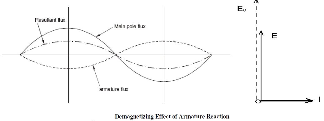
At zero lagging power factor loads the armature current is lagging by 90° with armature voltage. Under this condition, the position of armature conductor when inducing maximum emf is the center line of field mmf. Since there is no distortion but the two mmf are in opposition, the armature reaction is now purely demagnetizing as shown in Figure.


Phasor Diagrams

(c) Zero Power Factor Leading:-


Now at zero power factor leading, the armature current leads armature voltage by 90°. Under this condition, the mmf of armature as well as the field winding are in same phase and additive. The armature mmf has magnetizing effect due to leading armature current as shown in Figure.


Tags:armature reaction of alternator pdf ,armature reaction in ac machines,armature reaction in synchronous generator,armature reaction in alternator ppt,armature reaction in alternator animation,armature reaction in alternator at unity power factor wikipedia
Share:

Operation of Alternators:Principle and Working

Principle and Working of synchronous generator or alternator: 

Similar to the case of DC generator, the behavior of a Synchronous generator connected to an external load is different than that at no-load. In order to understand the performance of the Synchronous generator when it is loaded, consider the flux distributions in the machine when the armature also carries a current. 

Unlike in the DC machine in alternators the emf peak and the current peak will not occur in the same coil due to the effect of the power factor of the load. The current and the induced emf will be at their peaks in the same coil only for upf(unity power factor) loads.

For zero power factor lagging loads, the current reaches its peak in a coil which falls behind that coil wherein the induced emf is at its peak by 90 electrical degrees or half a pole-pitch. Likewise for zero power factor leading loads, the current reaches its peak in a coil which is ahead of that coil wherein the induced emf is at its peak by 90 electrical degrees or half a pole-pitch.

For simplicity, assume the resistance and leakage reactance of the stator windings to be negligible. Also assume the magnetic circuit to be linear i.e. the flux in the magnetic circuit is deemed to be proportional to the resultant ampere-turns - in other words the machine is operating in the linear portion of the magnetization characteristics.Thus the emf induced is the same as the terminal voltage, and the phase-angle between current and emf is determined only by the power factor (pf) of the external load connected to the synchronous generator.

Watch The Video For Clear Understanding(Working Principle of Alternator):- 


Tags:working principle of alternator pdf,difference between generator and alternator,working,principle of synchronous motor,working principle of alternator ppt working principle of alternator with diagrams,working principle of alternator in automobile alternator charge,advantage alternator
Share:

Harmonics:What are The Harmonics In Synchronous Machines

Harmonics Harmonics In Synchronous Machines:

Harmonics: When the uniformly sinusoidally distributed air gap flux is cut by either the stationary or rotating armature sinusoidal emf is induced in the alternator. Hence the nature of the waveform of induced emf and current is sinusoidal. But when the alternator is loaded waveform will not continue to be sinusoidal or becomes nonsinusoidal. Such nonsinusoidal wave form is called complex wave form.
By using Fourier series representation it is possible to represent complex nonsinusoidal waveform in terms of series of sinusoidal components called harmonics, whose frequencies are integral multiples of fundamental wave. The fundamental wave form is one which is having the frequency same as that of complex wave.The waveform, which is of the frequency twice that of the fundamental is called second harmonic. The one which is having the frequency three times that of the fundamental is called third harmonic and soon. These harmonic components can be represented as follows.

Fundamental: e1 = Em1 Sin ( t ± θ1)
2nd Hermonic e2 = Em2 Sin (2 t ± θ2)
3rd Harmonic e3 = Em3 Sin (3 t ± θ3)
5th Harmonic e5 = Em5 Sin (5 t ± θ5) etc.
In case of alternators as the field system and the stator coils are symmetrical the induced emf will also be symmetrical and hence the generated emf in an alternator will not contain any even harmonics.

Slot Harmonics: As the armature or stator of an alternator is slotted, some harmonics are induced into the emf which is called slot harmonics. The presence of slot in the stator makes the air gap reluctance at the surface of the stator non uniform. Since in case of alternators the poles are moving or there is a relative motion between the stator and rotor, the slots and the teeth alternately occupy any point in the air gap. Due to this the reluctance or the air gap will be continuously varying. Due to this variation of reluctance ripples will be formed in the air gap between the rotor and stator slots and teeth. This ripple formed in the air gap will induce ripple emf called slot harmonics.

Minimization Techniques of Harmonics: To minimize the harmonics in the induced waveforms following methods are employed:
1. Distribution of stator winding.
2. Short Chording
3. Fractional slot winding
4. Skewing
5. Larger air gap length.

Effect of Harmonics on induced emf:
The harmonics will affect both pitch factor and distribution factor and hence the induced emf. In a well designed alternator the air gap flux density distribution will be symmetrical and hence can be represented in Fourier series as follows.

The RMS value of the resultant voltage induced can be given as

Eph2 =  [(E1)2+ ....+ …………… (En)2]

**(A)2 Means A Square 

Effect of Harmonics of pitch and distribution Factor:
The pitch factor is given by Kp = cos /2, where is the chording angle.
For any harmonic say nth harmonic the pitch factor is given by Kpn = cos n α/2
The distribution factor is given by Kd = (sin mβ /2) / (m sin β/2)

For any harmonic say nth harmonic the distribution factor is given by Kdn = (sin mn β/2) / (m sin nβ /2)

This is the detailed info about Harmonics In Synchronous Machines,Minimization Methods of Harmonics.Effect of Harmonics on induced emf.

Tags:synchronous machines notes,synchronous machines ppt
synchronous machines nptel,synchronous machines video lectures,synchronous machines animation,synchronous machines ppt presentation wikipedia

Share:

Recent Posts

Unordered List

Definition List