Showing posts with label Transformer. Show all posts

Saturday, July 18, 2015

Sumpner's Test (Back to Back Test) on Transformer

Well, there are some methods to find out efficiency of transformers like OC & SC test on transformers,but they require direct loading on secondary.but in Sumpner's Test or Back to Back Test we apply phantom loading on transformer,so that we can save large amount of power from wasting.
Direct loading means the transformer is to be loaded to its rated capacity for specified number of hours to find out temperature rise.Hence, direct loading method of testing is normally not recommended especially for large capacity transformers as it involves huge amount of energy to be wasted only for testing of the transformer.

Sumpner's Test on Transformers :

In Sumpner's Test test two transformers are connected back to back means,primaries of two transformers connected in parallel and secondaries  side connected in series. 

Sumpner's test on transformer


So,one transformer is loaded on the other in Sumpner's Test.We connect AC supply at primary side of transformers.And one more low voltage supply is connected in series with secondaries to get the readings, as shown in the circuit diagram shown below.


  1. Refer above diagram,Name the two transformers as T1 and T2,and they are identical.Secondaries of them are connected in voltage opposition, i.e. E2 of first and E2 of secondary emf's cancel each other because transformers are identical. 
  2. In this case, as per superposition theorem,I1 & I2 vales are equal and in opposite direction,so resultant no current flows through secondary. And thus the no load test is simulated. The current drawn from V1 is 2I0, where I0 is equal to no load current of each transformer. Thus input power measured by wattmeter W1 is equal to iron losses of both transformers.

 Also Read:
  Buchholz Relay - Construction, Working 
  Different Types Of Transformers    
  Why Transformer Rating In KVA Not In KW?

i.e. iron loss per transformer Pi = W1/2.


  1. Now, a small voltage V2 supplied to secondary side from low voltage transformer. By adjusting voltage V2 make rated current I2 flows through the secondary. In this case, both primaries and secondaries carry rated current.
  2. Thus short circuit test is simulated and wattmeter W2 shows total full load copper losses of both transformers.


i.e. copper loss per transformer PCu = W2/2.


equation of full load efficiency of each transformer in Sumpner's Test is 

The indirect method or phantom loading method requires only iron and copper losses to be supplied corresponding to full load and still temperature rise corresponding to rated capacity of the transformer can be obtained. The only drawback is that it requires an additional and identical transformer for the transformer to be tested.These are the main advantages of sumpners or back to back test 
Share:

Saturday, July 4, 2015

Cooling Methods of Transformers

Cooling methods of transformer:


One of the major electrical machine in distribution system is power transformer.while operating transformer at high power ratings we experience heat comes from I²R losses of copper,hysteresis & eddy current  losses.we need to reduce this heat in transformers for efficient operation.In electrical power transformer we use different cooling methods of transformer to eliminate heat quickly.

There are different transformer cooling methods for various types of transformers.

Transformers can be divided in two types as 

(i) dry type transformers and 
(ii) oil immersed transformers. 

Different cooling methods of transformers are:- 

For dry type transformers
1.Air Natural (AN)
2.Air Blast(AB)
For oil immersed transformers
1.Oil Natural Air Natural (ONAN)
2.Oil Natural Air Forced (ONAF)
3.Oil Forced Air Forced (OFAF)
4.Oil Forced Water Forced  (OFWF)

There are different methods of cooling depends on transformer type.here at Learnelectrical.net Everything explained below.

Dry Type Transformers Cooling Methods:-

Cooling method for Air Natural or  Self Cooling (AN):-

This method uses atmospheric air as cooling medium.heat will be dispersed in air automatically.It is used for small rating transformers(ratings 1.5-3 MVA).

Air Blast(AB) Cooling Method:-

 In large transformers, cooling by natural air is difficult.in this process transformer located above the air chamber and a blast of compressed air is forced on core and winding with the help of blowers or fans. 

Cooling Methods for Oil Immersed Transformers:-

Oil Natural Air Natural (ONAN) Cooling Of Transformer:-

This method is used for oil immersed transformers.in this heat transferred from winding to oil in conventional way.heated oil flow in tubes of radiator,radiator will be cooled by natural air flowing between the radiator.the oil in transformer keeps circulating due to natural convection and dissipating heat in atmosphere due to natural conduction.

Oil Natural Air Forced (ONAF) Cooling Of Transformer:-

In oil forced air natural cooling system of transformer, the heat dissipation is accelerated by using forced air on the dissipating surface but circulation of the hot oil in transformer tank is natural convectional flow. In this method, the tank is made hollow and compressed air is blown into the hollow space to cool the transformer. The oil circulating inside takes heat to the tank walls.


Oil Forced Air Forced (OFAF) Cooling Of Transformer:-

In the external heat exchanger the compressed air is blasted with the help of fans to cool is the oil.Here the Oil and Air both are applied forcefully, but the hot oil follows a specific route for flowing. Convection channels are made closer to the winding of the transformer and the transformer oil is passed through those channels.

Oil Forced Water Forced (OFWF) Cooling Of Transformer:-

In this method  forced water flow is used to dissipate hear from the heat exchangers. The pressure oil is kept higher than water so oil mixes with water in case of leakage but water dose not mix with oil. Due to this method, smaller transformer size is sufficient as it is not necessary to employ water tubes inside the transformer tank. 

These are the most used electrical transformer cooling methods,which are efficient to cool major types of transformers.

Search: Cooling Methods of a Transformer,cooling methods of transformer pdf,cooling methods of transformer Wikipedia,cooling methods of transformer ppt,importance of transformer cooling methods

Share:

Friday, July 3, 2015

Auto Transformer Principle of Operation,Working

An auto transformer is a electrical transformer having only single winding which acts as both primary and secondary,so in input and output connected to shared single winding.

Why we need to go for Auto Transformer ?

We have some advantages of auto-transformer over normal two winding transformer.
1.Auto transformers usually smaller in size,because one winding is eliminated.
2.as size is small cost also low(so cheap in cost)
3.as the winding is same so leakage reactance will be less.
4.increased kVA rating.


Auto Transformer
Image Of Auto Transformer


Construction, Principle of Operation Of Auto Transformer: 

In Auto Transformer, one single winding is shared as primary winding as well as secondary winding.as in transformer copper wire wound on silicon steel.as shown in the figure input connected at fixed positions.but on other side we employ some tapping to get variable output voltages.Variable turns ratio at secondary can be obtained by changing the tappings of the winding.

Auto Transformer
Internal diagram of Auto Transformer 

Copper Savings in Auto Transformer:

If we compare conventional two winding transformer and  auto transformer the amount of copper needed for auto transformer is less.weight of copper of any winding depends upon its length and cross - sectional area.and length depends on no.of turns,cross - sectional area varies with rated current.

Auto Transformer

copper in the section AC proportional to, 

(N1-N2)I1

weight of copper in the section BC proportional to

(I1-I2)N2

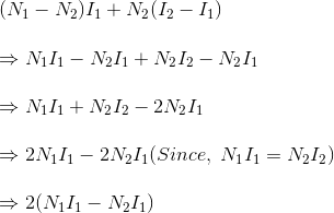
Hence, total weight of copper in the winding of auto transformer proportional to,


In similar way it can be proved, the weight of copper in two winding transformer is proportional to,


N1I1+N2I2
=2N1I1(Since, in a transformer N1I1=N2I2)

Let's assume, Wa and Wtw are weight of copper in auto transformer and two winding transformer respectively,


∴ Saving of copper in auto transformer compared to two winding transformer,
∴ Wtw -Wa=kWtw 
Share:

Wednesday, July 1, 2015

Parallel Operation Of Transformers

Parallel operation of transformers:

Parallel operation two or more transformers is can be achieved by connecting primary winding to common supply input and secondary to common load bus.sometimes parallel operation is economical to connect numbers of smaller rated transformers in parallel than installing a high rated electrical power transformer.so we go for parallel operation of transformers.
Why Parallel Operation of Transformers is required?
The first question why we need to operate transformers in parallel,reasons explained below.these are the main uses of Parallel Operation.
1.To maximize efficiency of the electrical power system. 
2.To maximize electrical power system availability.If numbers of transformers operated in parallel, we can shutdown or run any one of them for maintenance purpose,this gives various power output. 
3.To improve power system reliability.we can trip our load if any fault occur parallel operation gives reliable power supply.
4.To improve electrical power system flexibility.

Conditions For Parallel Operation of Single Phase Transformer:-

When want to operate two or more transformers in parallel, they must satisfy some conditions for high efficiency. These are the must followed conditions for parallel operation of transformers.

1.The first condition to be satisfied is voltage ratio of all connected transformers must be same.i.e their output voltage values may differ from each other but E2/E1 of first transformer must be equal to E2/E1 of second transformer. 

2.Transformers should be properly connected with regard to their polarities.The polarity of all connected transformers must be same in order to avoid circulating currents in transformers. 


3.The per unit or percentage impedance of the transformers should be equal.
4.The reactance/resistance ratios of the transformers should be the same.

You can get parallel operation of transformers pdf here.
Share:

Tuesday, June 30, 2015

Buchholz Relay - Construction, Working, Principle

Buchholz Relay:-

When we discuss about protection of transformer we come across buchholz relay first.What Is A Buchholz Relay?.Buchholz Relay is the major safety device of  transformer.it is pipe like construction  between the top of the transformer main tank and the conservator,employed in gas and oil operated transformer(rated >500 kVA).it prevents transformer from internal faults such as impulse breakdown of the insulating oil, insulation failure of turns,over heat of coils due to failure of windings etc.

Construction & Working of Buchholz Relay:-


Buchholz relay consists of an oil filled chamber with one inlet from transformer tank and one outlet to conservator. There are two hinged floats, one at the top of oil level and other at the bottom in the oil chamber. Each float is connected by a mercury switch. The upper float mercury switch which is connected to an alarm circuit and that on the lower float is connected to an external trip breaker. The schematic construction of a  buchholz relay is shown in the above fig.

Working Principle Of Buchholz Relay:-

Whenever there will be a minor internal fault such as impulse breakdown of the insulating oil, insulation failure of turns,core heating,over heat of coils due to failure of windings etc high amount of heat will be produced this heat heat decomposes the transformer insulating oil which results in production of gases like hydrocarbon gases, CO2 and CO.this gases occupies the area aboove the oil level which results in decrease in oil level.when oil level fall down to certain height alarm circuit will be energized.


Trip circuit will be energizes when phase to earth short circuit happens,baffle  plate or lower float will be closed.This switch energized the trip circuit of the circuit breakers associated with the transformer and immediately isolate the faulty transformer from the rest of the electrical power system by inter tripping the circuit breakers associated with both LV and HV sides of the transformer. This is functioning of  buchholz relay.

Advantages & Uses Of Buchholz Relay:-

1.Buchholz relay identifies the internal faults of transformer due to heating and it helps in avoiding the major faults by simple mechanical phenomenon.
2.Severity and type of the fault can be determined without even dismantling or disturbing  the transformer.
3.If a major fault occurs, the transformer can be isolated automatically with the help of buchholz relay to prevent accidents.
Share:

Wednesday, June 24, 2015

EMF Equation of Transformer

EMF Equation of Transformer :

Here is simple method to find out EMF Equation of Transformer:

Let            N1 = No. of turns in primary
                    N2 = No. of turns in secondary
                    Øm = Maximum flux in core in webers = Bm x A
                    f = Frequency of a.c. input in Hz.


The flux increases from it's zero value to maximum value Øm in one quarter of the cycle i.e. in 1/4 f second.

Therefore, r.m.s value of e.m.f./turn = 4.44 Øm volts

Now, r.m.s value of induced e.m.f in the whole primary winding 
                          = ( induced e.m.f. / turn ) x No. of primary winding

                               E1 = 4.44 f N1Øm ------------------- (i)

Similarly, r.m.s. value of e.m.f. induced in secondary is,

                               E2 = 4.44 f N2Øm ------------------- (ii) 

From the above equations (i) and (ii), we get  
E2/E1 = N2/N1 =k

the constant 'K' is called voltage transformation ratio .

1. If N2>N1 i.e. K>1 ,then transformer is called STEP-UP transformer .

2. If N2<N1 i.e. K<1 ,then transformer is called STEP-DOWN transformer .


Share:

Tuesday, June 16, 2015

Open Circuit(OC) And Short Circuit(SC) Test On Transformer

Open circuit and short circuit tests on single phase transformer:-

Why we need to conduct OC & SC test on transformers?

-To obtain the equivalent circuit parameters from Open circuit and short circuit tests , and to estimate efficiency & regulation at various loads.
-To understand the basic working principle of a transformer.
This method also called as indirect loading method of transformers.

Open Circuit Test (O.C. Test):-
This test mainly to find out 'no load loss (core loss)' and 'no load current I0'.it is also called no load test because we kept high voltage (HV) winding is kept open and the low voltage (LV) winding is connected to its power supply.to measure voltage,current,power wattmeter (W), ammeter (A) and voltmeter (V) are connected to the LV winding as shown in the above figure. 

1.Apply voltage to the LV side in steps up to the rated voltage and record primary current and power drawn from the source when voltage reached to rated value of the LV winding.
2.The ammeter reading gives the no load current I0. As I0 itself is very small, the voltage drops due to this current can be neglected.
3.The total power sending to the transformer is calculated by wattmeter (W),this reading is also sum of core losses and copper losses,beacuse no load is appiled on transformer so output is zero.
4.Hence, this input power only consists of core losses and copper losses.


Sometimes, a high resistance voltmeter is connected across the HV winding. Though, a voltmeter is connected, HV winding can be treated as open circuit as the current through the voltmeter is negligibly small. This helps in to find voltage transformation ratio (K).

The two components of no load current can be given as,

Iμ = I0sinΦ0   and    Iw = I0cosΦ0.

cosΦ0 (no load power factor) = W / (V1I0). ... (W = wattmeter reading)
From this, shunt parameters of equivalent circuit parameters of equivalent circuit of transformer (X0 and R0) can be calculated as
X0 = V1/Iμ  and  R0 = V1/Iw.

Short Circuit(SC)Or Impedance Test :-

The LV side of transformer is short circuited and wattmeter (W), voltmere (V) and ammeter (A) are connected on the HV side of the transformer.we short circuit only on LV side because to get high current,if we short circuit on HV side we get low current.

1.  As secondary is shorted, its resistance is very very small and on rated voltage it may draw very large current. Such large current can cause overheating and burning of the transformer. To limit this short circuit current, primary is supplied with low voltage which is just enough to cause rated current to flow through primary which can be observed on an ammeter. The low voltage can be adjusted with the help of variac. Hence this test is also called low voltage test or reduced voltage test. 

2.Voltage is applied to the HV side and increased from the zero until the ammeter reading equals the rated current.


Thus, the wattmeter reading can be taken as copper loss in the transformer.

Therefore, W = Isc2Req....... (where Req is the equivalent resistance of transformer)

 Zeq = Vsc/Isc.
Therefore, equivalent reactance of transformer can be calculated from the formula  Zeq2 = Req2 + Xeq2.
These, values are referred to the HV side of the transformer.
Hence, it is seen that the short circuit test gives copper losses of transformer and approximate equivalent resistance and reactance of the transformer.

Share:

Types Of Transformers : Different Types of Transformers

Different Types of Transformers

Transformers can be classified on different basis, like types of construction, types of cooling etc.

(A) On the basis of construction, transformers can be classified into two types as; 
(i) Core type transformer and (ii) Shell type transformer, which are described below.


(I) Core Type Transformer

In core type transformer, windings are cylindrical former wound, mounted on  the core limbs as shown in the figure above. The cylindrical coils have different layers and each layer is insulated from each other. Materials like paper, cloth or mica can be used for insulation. Low voltage windings are placed nearer to the core, as they are easier to insulate.

(Ii) Shell Type Transformer

The coils are former wound and mounted in layers stacked with insulation between them. A shell type transformer may have simple rectangular form (as shown in above fig), or  it may have a distributed form.

(B) On the basis of their purpose

Step up transformer: Voltage increases (with subsequent decrease in current) at secondary.
Step down transformer: Voltage decreases (with subsequent increase in current) at secondary.

(C) On the basis of type of supply
1.Single phase transformer
2.Three phase transformer

(D) On the basis of their use
1.Power transformer: Used in transmission network, high rating
2.Distribution transformer: Used in distribution network, comparatively lower rating than that of power transformers.
3.Instrument transformer: Used in relay and protection purpose in different instruments in industries
 Current transformer (CT)
Potential transformer (PT)
(E) On the basis of cooling employed 
Oil-filled self cooled type
Oil-filled water cooled type
Air blast type (air cooled)
Share:

Monday, June 15, 2015

Constructional features of Transformers

Constructional features of Transformers

Transformers used in practice are of extremely large variety depending upon the end use. In addition to the transformers used in power systems, in power transmission and distribution, a large number of special transformers are in use in applications like electronic supplies,rectification, furnaces, traction etc. Here the focus is on power transformers only.

The principle of operation of these transformers also is the same but the user requirements different .Here more common constructional aspects alone are discussed. Power transformers of smaller sizes could be air cooled while the larger ones are oil cooled. These machines are highly material intensive equipments and are designed to match the applications for best operating conditions. Hence they are `tailor made' to a job.This brings in a very large variety in their constructional features. Here more common constructional aspects alone are discussed.

These can be broadly divided into
1. Core construction
2. Winding arrangements
3. Cooling aspects
Share:

Why Transformer Rating In kVA, Not in KW?

The transformer is usually rated in terms of its input and output voltages and apparent power that it is designed to safely deliver. 

What are the meanings of these transformer ratings?

The voltage ratio indicates that the transformer has two windings, the high-voltage winding is rated for 1100 Volts and the low-voltage winding for 110 volts.
These voltages are proportional to their respective number of turns. Therefore, the voltage ratio also represents the turns ratio a or k.

Why Transformer Rating In kVA, Not in KW?

Answer is very simple transformer is a static device  two type of losses in a transformer;
1. Copper Losses
2. Iron Losses or Core Losses or  Insulation Losses.

Iron Losses or Core Losses or  Insulation Losses depends on Voltage while Copper losses ( I²R) are variable losses varies with Current passing through transformer windings.at the time of manufacturing its not decided that which kind of load will be added to transformer.We can't predict the power factor while designing the machine, because power factor depends upon the load which varies time to time.without including power factor we have to give rating so That’s why the Transformer Rating may be expressed in kVA, Not in kW.

Searches related:Why Transformer Rating In kVA, Not in KW?

why transformer neutral is grounded

why transformer is not rotating

why transformer rating in kva pdf

why transformer rating in kva and motor in hp

difference between kva and kw


Share:

What Is Transformer,Principle Of Working

Definition of Transformer:
Transformers are commonly used in applications which require the conversion of AC voltage from one voltage level to another (Step Up or Step Down),without changing frequency or constant frequency.
or
A transformer is a static electrical machine used for deliver power from one circuit to another without electrical coupling at constant frequency. 


For example, a farmer has a large, 480-V, 3-phase motor powering a well. The motor is in a building, and the farmer wants one 120-V circuit for a few lights and a receptacle outlet. A transformer is used to lower the voltage from 480 V to 120 V for the lighting circuit.


Working Principle Of Transformers:-


Transformers works on the principle of mutual induction.An important property of electricity is that a magnetic field is produced around a wire in which electrical current is flowing.The more current that flows, the stronger is the magnetic field. An even stronger magnetic field can be produced by winding the wire into a coil. Now the magnetic fields of adjacent wires add together to form one strong magnetic field. When a magnetic field moves across a wire, a voltage is induced into the wire.This is the most basic concept of the theory of transformer.

Here we take two coils named primary and secondary as shown in above figure,flux produces due to voltage in primary and voltage produce due to flux in core by following mutual induction.

Mutual Induction In Coils 

Mutual induction:-If the wire forms a complete circuit, current will flow in the wire. If a second coil of wire is placed in a moving magnetic field, then a voltage will be induced in this second coil. This phenomenon is called mutual induction.
Internal construction of transformers 

-Electrical energy is converted into magnetic field and then converted back into electrical energy in a second winding,with little or no loss of energy. 


 Also Read:
  Buchholz Relay - Construction, Working  
  OC & SC Test On Transformers   

Main Constructional Parts of Transformer:


The three main parts of a transformer are,

1.Primary Winding of transformer - which produces magnetic flux when it is connected to electrical source.

2.Magnetic Core of transformer - the magnetic flux produced by the primary winding, that will pass through this low reluctance path linked with secondary winding and create a closed magnetic circuit. 


3.Secondary Winding of transformer - the flux, produced by primary winding, passes through the core, will link with the secondary winding. This winding also wounds on the same core and gives the desired output of the transformer.

Types Of Power Transformer:-

Step Up Transformer:- This type of transformers we can only at power generation places to step up,because we generate power with  low voltage if we transmit low power losses will be high,so to reduce transmission losses we step up the voltage.transformers used to step up the voltage are called Step Up Transformers.

Step Down Transformer:-Transformers used to step down the voltage are called Step Down Transformers. we find at streets,sub stations,industries.

Uses of Power Transformer:-

-Transformer can rise or lower the level of level of Voltage or Current ( when voltage increases, current decreases and vice virsa because  P =V x I, and Power is same )  in an AC Circuit.

-Used in reduction of capital cost of the system and it also improves the voltage regulation of the transmission system.

-Transformer can increase or decrease the value of capacitor, an inductor or resistance in an AC circuit. It can thus act as an impedance transferring device.
  
-Transformer can be used to prevent DC from passing from one circuit to the other. 

-Transformer can isolate two circuits electrically.

Tags:what is transformer and its types,types of transformer,power transformer pdf,step up and step down transformer,types of transformer windings,electrical transformers types,applications of transformers,transformer working principle pdf
Share:

Recent Posts

Unordered List

Definition List