Showing posts with label D.C Motors. Show all posts

Monday, August 3, 2015

Brake Test on DC Shunt Motor:Efficiency By Direct Loading

In this method, the d.c. machine is loaded and output and input are measured to find the efficiency. For this purpose, two simple methods can be used.
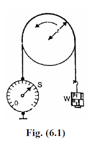
Brake test on dc machine:-

In this method, a brake is applied to a water-cooled pulley mounted on the motor shaft as shown in Fig.(6.1). One end of the rope is fixed to the floor via a spring balance S and a known mass is suspended at the other end. If the spring balance reading is S kg-Wt and the suspended mass has a weight of W kg-Wt,then,


Net pull on the rope = (W - S) kg-Wt = (W - S)*9.81 newtons
If r is the radius of the pulley in metres, then the shaft torque Tsh developed by

the motor is


Tsh = (W - S)*9.81*r N - m


If the speed of the pulley is N r.p.m., then,


Let V = Supply voltage in volts
I = Current taken by the motor in amperes
Input to motor = V I watts

(ii) In another method, the motor drives a calibrated generator i.e. one whose efficiency is known at all loads. The output of the generator is measured with the help of an ammeter and voltmeter.


Output of motor =Generator output/Generator efficiency.


Let V = Supply voltage is volts
I = Current taken by the motor is amperes
Input to motor = VI
Thus efficiency of the motor can be determined.
Because of several disadvantages (See Sec. 6.1), direct loading method is used

only for determining the efficiency of small machines.

Tags:theory of brake test on dc shunt motor,brake test on dc compound motor,break test on dc shunt motor,break test on dc shunt motor theory,dc motor evaluation,brake test on dc shunt motor viva
Share:

Wednesday, July 15, 2015

D.C. Machine Armature Windings

D.C. Machine Armature Windings

The different armature coils in a d.c. armature winding must be connected in series with each other by means of end connections (back connection and front connection) in a manner so that the generated voltages of the respective coils will aid each other in the production of the terminal e.m.f. of the winding.This windings are same in both DC motor and DC generator.

Two basic methods of making these end connections are:

1. Simplex lap winding.
2. Simplex wave winding.

1. Simplex lap winding.

lap winding diagram

For a simplex lap winding, the commutator pitch YC = 1 and coil span YS ~ pole pitch. Thus the ends of any coil are brought out to adjacent commutator segments and the result of this method of connection is that all the coils of the armature .ire in sequence with the last coil connected to the first coil.Consequently, closed circuit winding results. This is illustrated in Fig. where a part of the lap winding is shown. Only two coils are shown for simplicity. The name lap comes from the way in which successive coils overlap the preceding one.

2. Simplex wave winding

wave winding diagram
For a simplex wave winding, the commutator pitch YC ~ 2 pole pitches and coil span = pole pitch. The result is that the coils under consecutive pole pairs will be joined together in series thereby adding together their e.m.f.s [See Fig. 1.22].After passing once around the armature, the winding falls in a slot to the left or right of the starting point and thus connecting up another circuit. Continuing in this way, all the conductors will be connected in a single closed winding. This winding is called wave winding from the appearance (wavy) of the end connections.

Above we discussed difference between lap winding and wave winding briefly.

Search Terms: dc machine armature winding,dc motor armature winding pdf,dc motor armature winding diagram,dc motor armature winding animation

Share:

Friday, June 5, 2015

[*EASY*] Retardation Test or Running Down On D.C Machines

Retardation Test or Running Down On D.C Machines 

Retardation Test [Running Down Test] is used to find stray losses in D.C machines.this is one of the best method to find the mechanical (friction and windage) and iron losses of the machine.we can find efficiency by knowing armature and shunt copper losses at any given load current. 

Theory points to be noted of retardation test:

1. d.c. machine is run as a motor at a speed just above the normal.
2. then the supply to the armature is cut off while the field is normally excited. 
3. the speed is allowed to fall to some value just below normal. The time taken for this fall of speed is noted.

Circuit Diagram Running Down Test:


The armature consequently slows down and its kinetic energy is used in supplying the rotational or stray losses which includes iron, friction and winding loss.
       If I is the amount of inertia of the armature ans is the angular velocity.
      Kinetic energy of armature = 0.5 Iω2
 Rotational losses, W = Rate of change of kinetic energy
Moment of Inertia (I) of the Armature:
In retardation test, the rotational losses are given by:

                Retardation+test+dc+machines                  
        
In order to find W, the value of I must be known.to find I value we perform two methods.
  
W = 0.011 IN dN/dt.

Methods to find I value:

(a) Using Flywheel
(b) Without using Flywheel

Using Flywheel:

It is a fly-wheel method in which the value of I is calculated. First, retardation test is performed with armature alone and dN/dt1 is determined. Next, a flywheel of known moment of inertia I1 is keyed on to the shaft of the machine. For the same change in speed, dN/dt2 is noted. Since the addition of fly-wheel will not materially affect the rotational losses in the two cases,Since the values of I1,   t1  and   t2 are known, the moment of inertia I of the
armature can be determined.

Without using Flywheel:

In this method, I is eliminated from the expression by an experiment. First,
retardation test is performed with armature alone. The rotational losses are given by;

                          W = 0.011 IN dN/dt1

Next the motor is loaded with a known amount of power W' with a brake. For the same change in speed, dN/dt2 is noted. Then, Retardation test on dc machines.

Retardation+test+dc+machines

  • Since the values of W', t1 and t2 are known, the value of W can be determined.
  • Here dN/dt1 is rate of change in speed without extra load whereas dN/dt2 is rate change in speed with extra electrical load which provides retarding torque.

Tags:Retardation Test On D.C Machines Wikipedia,Retardation or Running down test on d.c machines,lab manual,retardation test on dc shunt motor theory
Share:

Recent Posts

Unordered List

Definition List