Wednesday, September 16, 2015

Simple Loop Generator Principle,Working

Simple Loop Generator Principle

An electrical generator is a machine which converts mechanical energy (or power) into electrical energy (or power).The energy conversion is based on the principle of the production of dynamically (or due to motion) induced e.m.f.whenever a conductor cuts magnetic flux, dynamically induced e.m.f. is produced in it according to Faraday’s Laws of Electromagnetic Induction. This e.m.f. causes a current to flow if the conductor circuit is closed. Hence, two basic essential parts of an electrical dc generator are (i) a magnetic field and (ii) a conductor or conductors which can so move as to cut the flux.


Simple Loop Generator Construction

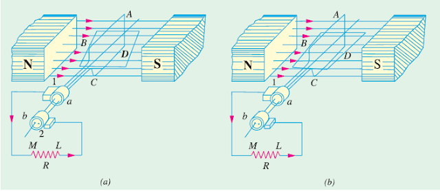
In Fig.is shown a single-turn rectangular copper coil ABCD rotating about its own axis in a magnetic field provided by either permanent magnet is or electromagnets. The two ends of the coil are joined to two slip-rings ‘a’ and ‘b’ which are insulated from each other and from the central shaft. Two collecting brushes (of carbon or copper) press against the slip-rings. Their function is to collect the current induced in the coil and to convey it to the external load resistance R. The rotating coil may be called ‘armature’ and the magnets as ‘field magnets’. 

Fig.0

DC Generator Working:

Imagine the coil to be rotating in clock-wise direction (Fig.1). As the coil assumes successive positions in the field, the flux linked with it changes. Hence, an e.m.f. is induced in it which is proportional to the rate of change of flux linkages (e = NdΦdt). When the plane of the coil is at right angles to lines of flux i.e. when it is in position, 1, then flux linked with the coil is maximum but rate of change of flux linkages is minimum. It is so because in this position, the coil sides AB and CD do not cut or shear the flux, rather they slide along them i.e. they move parallel to them. Hence, there is no induced e.m.f. in the coil. Let us take this no-e.m.f. or vertical position of the coil as the starting position. The angle of rotation or time will be measured from this position.


Fig.1

As the coil continues rotating further, the rate of change of flux linkages (and hence induced e.m.f. in it) increases, till position 3 is reached where θ = 90º. Here, the coil plane is horizontal i.e. parallel to the lines of flux. As seen, the flux linked with the coil is minimum but rate of change of flux linkages is maximum. Hence, maximum e.m.f. is induced in the coil when in this position
(Fig.1).

In the next quarter revolution i.e. from 90º to 180º, the flux linked with the coil gradually increases but the rate of change of flux linkages decreases. Hence, the induced e.m.f. decreases gradually till in position 5 of the coil, it is reduced to zero value. So, we find that in the first half revolution of the coil, no (or minimum) e.m.f. is induced in it when in position 1, maximum when in position 3 and no e.m.f. when in position 5. The direction of
this induced e.m.f. can be found by applying Fleming’s Right-hand rule which gives its direction from A to B and C to D. Hence, the direction of current flow is ABMLCD (Fig.0). The current through the load resistance R flows from M to L during the first half revolution of the coil.

In the next half revolution i.e. from 180º to 360º, the variations in the magnitude of e.m.f. are similar to those in the first half revolution. Its value is maximum when coil is in position 7 and minimum when in position 1. But it will be found that the direction of the induced current is from D to C and B to A as shown in Fig.1. Hence, the path of current flow is along DCLMBA which is just the reverse of the previous direction of flow. Therefore, we find that the current which we obtain from such a simple generator reverses its direction after every half revolution. Such a current undergoing periodic reversals is known as alternating current. It is, obviously, different from a direct current which continuously flows in one and the same direction.

It should be noted that alternating current not only reverses its direction, it does not even keep its magnitude constant while flowing in any one direction. The two half-cycles may be called positive and negative half-cycles respectively (Fig.1). For making the flow of current unidirectional in the external circuit, the slip-rings are replaced by split-rings (Fig.2). The split-rings are made out of a conducting cylinder which is cut into two halves or segments insulated from each other by a thin sheet of mica or some other insulating material (Fig.2).

(Fig.2)

As before, the coil ends are joined to these segments on which rest the carbon or copper brushes. It is seen [Fig.(a)] that in the first half revolution current flows along (ABMNLCD) i.e. the brush No. 1 in contact with segment ‘a’ acts as the positive end of the supply and ‘b’ as the negative end. In the next half revolution [Fig.(b)], the direction of the induced current in the coil has reversed. But at the same time, the positions of segments ‘a’ and ‘b’ have also reversed with the result that brush No. 1 comes in touch with the segment which is positive i.e. segment ‘b’ in this case. Hence, current in the load resistance again flows from M to L. The waveform of the current through the external circuit is as shown in Fig.. This current is unidirectional but not continuous like pure direct current.


Fig.3

It should be noted that the position of brushes is so arranged that the change over of segments ‘a’ and ‘b’ from one brush to the other takes place when the plane of the rotating coil is at right angles to the plane of the lines of flux. It is so because in that position, the induced e.m.f. in the coil is zero. Another important point worth remembering is that even now the current induced in the coil sides is alternating as before. It is only due to the rectifying action of the split-rings (also called commutator) that it becomes unidirectional in the external circuit. Hence, it should be clearly understood that even in the armature of a d.c. generator, the induced voltage is alternating.

Share:

Tuesday, September 15, 2015

Skin Effect of Conductors In Transmission Lines

Skin Effect of Conductors In Transmission Lines

When a conductor is carrying steady direct current (d.c.), this current is uniformly distributed over the whole X-section of the conductor. However, an alternating current flowing through the conductor does not distribute uniformly, rather it has the tendency to concentrate near the surface of the conductor as shown in Fig. This is known as skin effect in transmission lines.
The tendency of alternating current to concentrate near the surface of a conductor is known as skin effect.

                                skin effect

Due to skin effect, the effective area of cross-section of the conductor through current flows is reduced. Consequently, the resistance of the conductor is slightly increased when carrying an alternating current. The cause of skin effect can be easily explained. A solid conductor may be thought to be consisting of a large number of strands, each carrying a small part of the current. The inductance of each strand will vary according to its position. Thus, the strands near the center are surrounded by a greater magnetic flux and hence have larger inductance than that near the surface. The high reactance of inner strands causes the alternating current to flow near the surface of conductor. This crowding of current near the conductor surface is the skin effect.

Skin effect depends upon the following factors :

(i) Nature of material
(ii) Diameter of wire − increases with the diameter of wire.
(iii) Frequency − increases with the increase in frequency.
(iv) Shape of wire − less for stranded conductor than the solid conductor.
It may be noted that skin effect is negligible when the supply frequency is low (< 50 Hz) and conductor diameter is small (< 1cm).
Share:

Monday, August 3, 2015

Why We Can’t Store AC Voltages ?

Why we can not store AC like DC

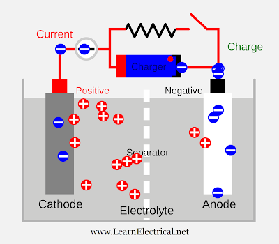
Before going to discussion on "why we can't store ac current in batteries" understand what is AC & DC voltages.AC voltage changes it's polarity 50-60 times per second (50Hz for India,UK & 60Hz for USA).But DC is constant voltage with respect to time.If we consider charging mechanism of electro-chemical cell or battery,it is continuous process of injecting electrons on negative side(-Ve) plate and protons positive side(+Ve) plate.
AC voltage changes it's polarity 50-60 times per second battery cannot change their terminals with 50-60 Hz speed to maintain AC output.so that’s why we can’t store AC in Batteries.


We cannot store AC in batteries because AC changes their polarity up to 50-60(depends on frequency) times in a second.Storing of charges will not happen as in a cycle charging and discharging happens  when we connect a battery with AC supply,.so average current stored in battery is zero,that's why we can't store AC in batteries.However AC can be stored in capacitor or inductor but this is not much efficient.so we have only DC batteries in our power system.
Share:

Brake Test on DC Shunt Motor:Efficiency By Direct Loading

In this method, the d.c. machine is loaded and output and input are measured to find the efficiency. For this purpose, two simple methods can be used.

Brake test on dc machine:-

In this method, a brake is applied to a water-cooled pulley mounted on the motor shaft as shown in Fig.(6.1). One end of the rope is fixed to the floor via a spring balance S and a known mass is suspended at the other end. If the spring balance reading is S kg-Wt and the suspended mass has a weight of W kg-Wt,then,


Net pull on the rope = (W - S) kg-Wt = (W - S)*9.81 newtons
If r is the radius of the pulley in metres, then the shaft torque Tsh developed by

the motor is


Tsh = (W - S)*9.81*r N - m


If the speed of the pulley is N r.p.m., then,


Let V = Supply voltage in volts
I = Current taken by the motor in amperes
Input to motor = V I watts

(ii) In another method, the motor drives a calibrated generator i.e. one whose efficiency is known at all loads. The output of the generator is measured with the help of an ammeter and voltmeter.


Output of motor =Generator output/Generator efficiency.


Let V = Supply voltage is volts
I = Current taken by the motor is amperes
Input to motor = VI
Thus efficiency of the motor can be determined.
Because of several disadvantages (See Sec. 6.1), direct loading method is used

only for determining the efficiency of small machines.

Tags:theory of brake test on dc shunt motor,brake test on dc compound motor,break test on dc shunt motor,break test on dc shunt motor theory,dc motor evaluation,brake test on dc shunt motor viva
Share:

Saturday, July 18, 2015

Sumpner's Test (Back to Back Test) on Transformer

Well, there are some methods to find out efficiency of transformers like OC & SC test on transformers,but they require direct loading on secondary.but in Sumpner's Test or Back to Back Test we apply phantom loading on transformer,so that we can save large amount of power from wasting.
Direct loading means the transformer is to be loaded to its rated capacity for specified number of hours to find out temperature rise.Hence, direct loading method of testing is normally not recommended especially for large capacity transformers as it involves huge amount of energy to be wasted only for testing of the transformer.

Sumpner's Test on Transformers :

In Sumpner's Test test two transformers are connected back to back means,primaries of two transformers connected in parallel and secondaries  side connected in series. 

Sumpner's test on transformer


So,one transformer is loaded on the other in Sumpner's Test.We connect AC supply at primary side of transformers.And one more low voltage supply is connected in series with secondaries to get the readings, as shown in the circuit diagram shown below.


  1. Refer above diagram,Name the two transformers as T1 and T2,and they are identical.Secondaries of them are connected in voltage opposition, i.e. E2 of first and E2 of secondary emf's cancel each other because transformers are identical. 
  2. In this case, as per superposition theorem,I1 & I2 vales are equal and in opposite direction,so resultant no current flows through secondary. And thus the no load test is simulated. The current drawn from V1 is 2I0, where I0 is equal to no load current of each transformer. Thus input power measured by wattmeter W1 is equal to iron losses of both transformers.

 Also Read:
  Buchholz Relay - Construction, Working 
  Different Types Of Transformers    
  Why Transformer Rating In KVA Not In KW?

i.e. iron loss per transformer Pi = W1/2.


  1. Now, a small voltage V2 supplied to secondary side from low voltage transformer. By adjusting voltage V2 make rated current I2 flows through the secondary. In this case, both primaries and secondaries carry rated current.
  2. Thus short circuit test is simulated and wattmeter W2 shows total full load copper losses of both transformers.


i.e. copper loss per transformer PCu = W2/2.


equation of full load efficiency of each transformer in Sumpner's Test is 

The indirect method or phantom loading method requires only iron and copper losses to be supplied corresponding to full load and still temperature rise corresponding to rated capacity of the transformer can be obtained. The only drawback is that it requires an additional and identical transformer for the transformer to be tested.These are the main advantages of sumpners or back to back test 
Share:

Wednesday, July 15, 2015

E.M.F. Equation of a D.C. Generator

We shall now derive an expression for the e.m.f. generated in a d.c. generator.
Let Ø= flux/pole in Wb
Z = total number of armature conductors
P = number of poles
A = number of parallel paths = 2 ... for wave winding
= P ... for lap winding
N = speed of armature in r.p.m.
Eg = e.m.f. of the generator = e.m.f./parallel path
Flux cut by one conductor in one revolution of the armature,
dØ = PØ webers
Time taken to complete one revolution,
dt = 60/N second
e.m.f generated/conductor = dØ/dt=PØ/{60/N}=PØN/60

e.m.f. equation of generator

Eg = e.m.f. per parallel path= (e.m.f/conductor) ´ No. of conductors in series per parallel path.

Eg=PØN/60*(Z/A)

 Also Read:
  EMF Equation of Transformer 
  How Does DC Generator Works?
  Unseen DC Windings     
Search:e.m.f. equation of generator pdf,e.m.f. equation of generator derivation,e.m.f. equation of generator easy way ,emf of dc generator
Share:

D.C. Machine Armature Windings

D.C. Machine Armature Windings

The different armature coils in a d.c. armature winding must be connected in series with each other by means of end connections (back connection and front connection) in a manner so that the generated voltages of the respective coils will aid each other in the production of the terminal e.m.f. of the winding.This windings are same in both DC motor and DC generator.

Two basic methods of making these end connections are:

1. Simplex lap winding.
2. Simplex wave winding.

1. Simplex lap winding.

lap winding diagram

For a simplex lap winding, the commutator pitch YC = 1 and coil span YS ~ pole pitch. Thus the ends of any coil are brought out to adjacent commutator segments and the result of this method of connection is that all the coils of the armature .ire in sequence with the last coil connected to the first coil.Consequently, closed circuit winding results. This is illustrated in Fig. where a part of the lap winding is shown. Only two coils are shown for simplicity. The name lap comes from the way in which successive coils overlap the preceding one.

2. Simplex wave winding

wave winding diagram
For a simplex wave winding, the commutator pitch YC ~ 2 pole pitches and coil span = pole pitch. The result is that the coils under consecutive pole pairs will be joined together in series thereby adding together their e.m.f.s [See Fig. 1.22].After passing once around the armature, the winding falls in a slot to the left or right of the starting point and thus connecting up another circuit. Continuing in this way, all the conductors will be connected in a single closed winding. This winding is called wave winding from the appearance (wavy) of the end connections.

Above we discussed difference between lap winding and wave winding briefly.

Search Terms: dc machine armature winding,dc motor armature winding pdf,dc motor armature winding diagram,dc motor armature winding animation

Share:

Recent Posts

Unordered List

Definition List