Saturday, July 18, 2015

Sumpner's Test (Back to Back Test) on Transformer

Well, there are some methods to find out efficiency of transformers like OC & SC test on transformers,but they require direct loading on secondary.but in Sumpner's Test or Back to Back Test we apply phantom loading on transformer,so that we can save large amount of power from wasting.
Direct loading means the transformer is to be loaded to its rated capacity for specified number of hours to find out temperature rise.Hence, direct loading method of testing is normally not recommended especially for large capacity transformers as it involves huge amount of energy to be wasted only for testing of the transformer.

Sumpner's Test on Transformers :

In Sumpner's Test test two transformers are connected back to back means,primaries of two transformers connected in parallel and secondaries  side connected in series. 

Sumpner's test on transformer


So,one transformer is loaded on the other in Sumpner's Test.We connect AC supply at primary side of transformers.And one more low voltage supply is connected in series with secondaries to get the readings, as shown in the circuit diagram shown below.


  1. Refer above diagram,Name the two transformers as T1 and T2,and they are identical.Secondaries of them are connected in voltage opposition, i.e. E2 of first and E2 of secondary emf's cancel each other because transformers are identical. 
  2. In this case, as per superposition theorem,I1 & I2 vales are equal and in opposite direction,so resultant no current flows through secondary. And thus the no load test is simulated. The current drawn from V1 is 2I0, where I0 is equal to no load current of each transformer. Thus input power measured by wattmeter W1 is equal to iron losses of both transformers.

 Also Read:
  Buchholz Relay - Construction, Working 
  Different Types Of Transformers    
  Why Transformer Rating In KVA Not In KW?

i.e. iron loss per transformer Pi = W1/2.


  1. Now, a small voltage V2 supplied to secondary side from low voltage transformer. By adjusting voltage V2 make rated current I2 flows through the secondary. In this case, both primaries and secondaries carry rated current.
  2. Thus short circuit test is simulated and wattmeter W2 shows total full load copper losses of both transformers.


i.e. copper loss per transformer PCu = W2/2.


equation of full load efficiency of each transformer in Sumpner's Test is 

The indirect method or phantom loading method requires only iron and copper losses to be supplied corresponding to full load and still temperature rise corresponding to rated capacity of the transformer can be obtained. The only drawback is that it requires an additional and identical transformer for the transformer to be tested.These are the main advantages of sumpners or back to back test 
Share:

Wednesday, July 15, 2015

E.M.F. Equation of a D.C. Generator

We shall now derive an expression for the e.m.f. generated in a d.c. generator.
Let Ã˜= flux/pole in Wb
Z = total number of armature conductors
P = number of poles
A = number of parallel paths = 2 ... for wave winding
= P ... for lap winding
N = speed of armature in r.p.m.
Eg = e.m.f. of the generator = e.m.f./parallel path
Flux cut by one conductor in one revolution of the armature,
dØ = PØ webers
Time taken to complete one revolution,
dt = 60/N second
e.m.f generated/conductor = dØ/dt=PØ/{60/N}=PØN/60

e.m.f. equation of generator

Eg = e.m.f. per parallel path= (e.m.f/conductor) ´ No. of conductors in series per parallel path.

Eg=PØN/60*(Z/A)

 Also Read:
  EMF Equation of Transformer 
  How Does DC Generator Works?
  Unseen DC Windings     
Search:e.m.f. equation of generator pdf,e.m.f. equation of generator derivation,e.m.f. equation of generator easy way ,emf of dc generator
Share:

D.C. Machine Armature Windings

D.C. Machine Armature Windings

The different armature coils in a d.c. armature winding must be connected in series with each other by means of end connections (back connection and front connection) in a manner so that the generated voltages of the respective coils will aid each other in the production of the terminal e.m.f. of the winding.This windings are same in both DC motor and DC generator.

Two basic methods of making these end connections are:

1. Simplex lap winding.
2. Simplex wave winding.
1. Simplex lap winding.

lap winding diagram

For a simplex lap winding, the commutator pitch YC = 1 and coil span YS ~ pole pitch. Thus the ends of any coil are brought out to adjacent commutator segments and the result of this method of connection is that all the coils of the armature .ire in sequence with the last coil connected to the first coil.Consequently, closed circuit winding results. This is illustrated in Fig. where a part of the lap winding is shown. Only two coils are shown for simplicity. The name lap comes from the way in which successive coils overlap the preceding one.

2. Simplex wave winding

wave winding diagram
For a simplex wave winding, the commutator pitch YC ~ 2 pole pitches and coil span = pole pitch. The result is that the coils under consecutive pole pairs will be joined together in series thereby adding together their e.m.f.s [See Fig. 1.22].After passing once around the armature, the winding falls in a slot to the left or right of the starting point and thus connecting up another circuit. Continuing in this way, all the conductors will be connected in a single closed winding. This winding is called wave winding from the appearance (wavy) of the end connections.

Above we discussed difference between lap winding and wave winding briefly.

Search Terms: dc machine armature winding,dc motor armature winding pdf,dc motor armature winding diagram,dc motor armature winding animation

Share:

Saturday, July 11, 2015

Type of Electrical Poles : Overhead Line Supports

Type of Electrical Poles : Overhead Line Supports 

Overhead transmission lines requires some support to carry the conductors.The supporting structures for overhead transmission line conductors are various types of poles and towers called line supports or electrical poles.

Properties of Line Supports :-

(i) Line Supports should have high mechanical strength to withstand the weight of conductors and wind loads etc.
(ii) Light in weight without the loss of mechanical strength.
(iii) Poles should be cheaper in cost and eco-friendly .
(iv)High life time because frequent replacement of poles may economical .
(v) Easy accessibility of conductors for maintenance.

Various types of poles:-

We have different types of electrical poles to carry various types of conductors,we can't use any one of the below line support for all types of conductors. 
1.Wooden poles
2.Steel poles
3.R.C.C. poles 
4.Lattice steel towers.

1. Wooden poles:-


Wooden poles are made of wood (sal or chir) and are suitable for lines short distance (up to 50m) and less area lines.wooden pole supports are cheap in cost,easily available, provide natural insulating properties and moreover economical.The wooden poles generally tend to rot below the ground level, causing foundation failure. In order to prevent this, the portion of the pole below the ground level is impregnated with preservative compounds like creosote oil.but now a days these poles are out of use,they are replaced by R.C.C poles because of their long life.

Disadvantages of wooden supports are :

(i) tendency to rot below the ground level
(ii) comparatively smaller life (20-25 years)
(iii) cannot be used for voltages higher than 20 kV
(iv) less mechanical strength and 
(v) require periodical inspection.

2. Steel poles:

The steel poles are used as a replacement for wooden poles.Because steel poles possess greater mechanical strength, longer life than wooden poles and able to withstand longer spans.These poles are generally used for distribution purposes in the cities. This type of supports need to be galvanised or painted in
order to prolong its life.
The steel poles are of three types viz., 
(i) rail poles
(ii) tubular poles and
(iii) rolled steel joints.

3.RCC poles: 

RCC stands for reinforced concrete.These poles have become very popular as line supports in recent years.They have greater mechanical strength, longer life and permit longer spans than steel poles. Moreover, they give good outlook, require little maintenance and have good insulating properties.Expect high weight and manufacturing cost they are very good alternative for all types of line supports.

4.Steel towers: 

In practice, wooden, steel and reinforced concrete poles are used for distribution
purposes at low voltages, say upto 11 kV.To transmit higher voltages than 11kv we use steel tower.Steel towers have greater mechanical strength, longer life, can withstand most severe climatic conditions and permit the use of longer spans and we can increase or decrease length of the pole by assembling some more cross arms.these are more efficient but requires more space to establish.

These are the different types of electric poles which we can see in daily observations.
Share:

Thursday, July 9, 2015

String Efficiency & Improving Methods

String Efficiency:

The total voltage applied across the string of suspension type insulators is not equally distributed across all discs.In this distribution of voltage, disc nearest to the conductor will be at higher potential than the other discs. This unequal potential distribution is undesirable and is usually expressed in terms of string efficiency

What Is String Efficiency?

"The ratio of voltage across the whole string to the product of number of discs and the voltage across the disc nearest to the conductor is known as string efficiency."
i.e.,String efficiency =Voltage across the string/(n ×Voltage across disc nearest to conductor)
Where n = number of discs in the string.

String efficiency is an important factor is transmission line designing.since it decides the potential distribution along the string.to get uniform distribution string efficiency should be high.Thus 100% string efficiency is an ideal case for which the volatge across each disc will be exactly the same.that gives easy calculations to no.of discs to be added.but it is impossible to achieve 100% string efficiency,yet efforts should be made to improve it as close to this value as possible.

Mathematical expression for String Efficiency:-

Above Fig. shows the equivalent circuit for a 3-disc string. Let us suppose that self capacitance of each disc is C. Let us further assume that shunt capacitance C1 is some fraction K of selfcapacitance i.e., C1 = KC. Starting from the cross arm or tower, the voltage across each unit is V1,V2 and V3 respectively as shown. 
Applying Kirchhoff’s current law to node A, we get,

I2 = I1 + i1
or V2ω C* = V1ω C + V1ω C1
or V2ω C = V1ω C + V1ω K C
∴ V2 = V1 (1 + K) ...(i)

Applying Kirchhoff’s current law to node B, we get
I3 = I2 + i2
or V3 ω C = V2ω C + (V1 + V2) ω C1 
or V3 ω C = V2ω C + (V1 + V2) ω K C
or V3 = V2 + (V1 + V2)K
= KV1 + V2 (1 + K)
= KV1 + V1 (1 + K)2   since [ V2 = V1 (1 + K)]
= V1 [K + (1 + K)²]
∴ V3 = V1[1 + 3K + K²] ...(ii)
Voltage between conductor and earth (i.e., tower) is
V = V1 + V2 + V3
= V1 + V1(1 + K) + V1 (1 + 3K + K²)
= V1 (3 + 4K + K²)
∴ V = V1(1 + K) (3 + K) ...(iii)
From expressions (i), (ii) and (iii), we get,
 V1/1=V2/(1+K)=V3/(1 + 3K + K²)=V/(1+K)(3=K)

∴Voltage across top unit, V1 = V/(1 + K)(3 + K)
Voltage across second unit from top, V2 = V1 (1 + K)

Voltage across third unit from top, V3 = V1 (1 + 3K + K²)
%age String efficiency =Voltage across the string*100/(n ×Voltage across disc nearest to conductor)
=V*100/3V3


Methods of Improving String Efficiency:

By using longer cross-arms:-
From above observation we can say The value of string efficiency depends upon the value of K i.e., ratio of shunt capacitance to mutual capacitance.For the low the value of K, the string efficiency will be high and we get uniform voltage distribution.value of K can be decreased by reducing the shunt capacitance. In order to reduce shunt capacitance, the distance of conductor from tower must be increased i.e., longer cross-arms should be used.

By grading the insulators:-
In this method, different dimensions of  insulators are chosen which have different capacitance. The insulators are capacitance graded i.e. they are assembled in the string in such a way that the top unit has the minimum capacitance, increasing progressively as the bottom unit (i.e., nearest to conductor) is reached. Since voltage is inversely proportional to capacitance, this method tends to equalize the potential distribution across the units in the string. This method has the disadvantage that a large number of different-sized insulators are required.
By using a guard ring:-
The potential across each unit in a string can be equalized by using a guard ring which is a metal ring electrically connected to the conductor and surrounding the bottom insulator. The guard ring is contoured in such a way that shunt capacitance currents i1, i2 etc. are equal to metal fitting line capacitance currents i′1, i′2 etc. The result is that same charging current I flows through each unit of string. Consequently, there will be uniform potential distribution across the units.

Related:
string efficiency in power system
string efficiency formula
string efficiency of suspension insulators
string efficiency in power system pdf
string efficiency transmission line
string efficiency of insulators ppt
string efficiency ppt
Share:

Wednesday, July 8, 2015

Types of Insulators In Overhead Transmission Lines

Types of Insulators In Overhead Transmission Lines

Transmission line insulators separate, contain and suspend transmission line conductors.they protects short circuit path between earth and transmission line.There are several types of insulators In overhead transmission lines.but the most know are pin type, suspension type, strain insulator,shackle insulator and Stay Insulator.

Types of electrical insulators in transmission lines:

1. Pin type insulators:


The name "pin" came from constructional design of it.Pin type insulators are used for the transmission of lower voltages.transmission range of pin type is up to 33 kV (kilovolts).Pin type insulators are secured with steel or lead bolts onto transmission poles. These are typically used for straight-running transmission lines.There is a groove on the upper end of the insulator for housing the conductor. The conductor passes through this groove and is bound by the annealed wire of the same material as the conductor.we can use this type of insulator beyond 33kv,but that becomes bulky in size & costly. 


2.Suspension type insulators :


Suspension type insulators are used to transmit above 33kv.because above 33kv using of pin type is uneconomical.In suspension type insulator numbers of insulators are connected in series to form a string and the conductor is suspended at the bottom end of this string while the other end of the string is secured to the cross-arm of the tower.Each insulator of a suspension string is called disc.


Advantages of Suspension Type insulators :

(i)Suspension type insulators are very economical voltages beyond 33 kV.

(ii) Each unit or disc of suspension type insulator is designed for low voltage,usually 11 kV.As per requirement of operating voltage we can add no.of discs in series. 

(iii) If any one disc is damaged, the whole string does not become useless because the damaged disc can be replaced by the sound one.

(iv) The suspension arrangement provides greater flexibility to the line. The connection at the cross arm is such that insulator string is free to swing in any direction and can take up the position where mechanical stresses are minimum.

(v) The suspension type insulators are generally used with steel towers. As the conductors run below the earthed cross-arm of the tower, therefore, this arrangement provides partial protection from lightning.

3.Strain Type insulators:


Strain type insulators are simply horizontally suspended suspension insulators.When there is a dead end or there is a sharp corner in transmission line, the line has to sustain a great  tensile load of conductor or strain.The discs of strain insulators are used in the vertical plane. When the tension in lines is exceedingly high, at long river spans, two or more strings are used in parallel.voltage rating almost equal to suspension type.

4.Shackle Type Insulators:


Shackle type insulators, similar to strain type insulators, are used on sharp curves, end poles and in section poles.These insulators are single, round porcelain parts that are mounted horizontally or vertically.The shackle insulator or spool insulator is usually used in low voltage distribution system.They can be directly fixed to the pole with a bolt or to the cross arm.

5.Stay insulators :

The insulator used in the stay wire is called as the stay insulator and is usually of porcelain and is so designed that in case of breakage of the insulator the guy-wire will not fall to the ground.

This Is Complete Information On Types of Electrical Insulators ; Insulators In Overhead Transmission Lines.


Tags: types of electrical insulators ppt,types of electrical insulators pdf,types of electrical wire,function electrical insulators,benefits electrical insulators,invented electrical insulators,insulators electrical electronic applications,what is an insulator of electricity
Share:

DC Generator : Working,Principle

DC Generator : Working,Principle 

An electrical generator is a machine which converts mechanical energy (or power) into electrical energy (or power).DC generator works on the principle of Faraday's Laws of Electromagnetic Induction.

Faraday's Laws of Electromagnetic Induction:

According faraday's laws whenever a conductor cuts magnetic flux. dynamically induced e.m.f. is produced in it.this e.m.f. causes a current to flow if the conductor circuit is closed.energy conversion in the generator is based on the principle of the production of dynamically (or motionally) induced e.m.f in armature.

the amount of emf generated is 
E=dφ/dt

We have two basic essential parts of an DC generator are 
i) a magnetic field and (ii) a conductor or conductors which can so move as to cut the flux. 

DC Generator Working Principle:

Working principle of dc generator can be explained with single loop generator concept.let us consider single loop coil inserted in magnetic (N-S)field as shown in the figure.assign loop edges with ABCD as marked..the magnetic field direction will be from N-S.assume you are rotating the coil
Step1:-


In this mode the dφ is maximum,because AB and CD are parallel to magnetic filed direction.field strength at CD and AB are not same so dφ exist.the out put voltage we E=dφ/dt.the current direction will be given by  current can be determined by Flemming's right hand Rule. This rule says that is you stretch thumb, index finger and middle finger of your right hand perpendicular to each other, then thumbs indicates the direction of motion of the conductor, index finger indicates the direction of magnetic field,from Flemming's right hand Rule current flow from A to B ,C to D.
 Step2:-


In this mode the dφ is minimum,because AB and CD are perpendicular to magnetic filed direction.field strength at CD and AB are same so dφ almost zero.hence we assume current is also zero.
Step3:-


In this mode the dφ is maximum,because AB and CD are parallel to magnetic filed direction.field strength at CD and AB are not same so dφ exist.the out put voltage we E=dφ/dt.the current direction will be given by  current can be determined by Flemming's right hand Rule. Flemming's right hand Rule current flow from B to A ,D to C.

ALL DONE..but observe Step1 and Step3 we are getting AC in DC generator instead of DC to eliminate bi directional current we use slip rings.by using slip ring we convert bi directional current into uni directional current.Split ring are made out of a conducting cylinder which cuts into two halves or segments insulated from each other. The external load terminals are connected with two carbon brushes which are rest on these split slip ring segments.

DC Generator with slip rings:

DC Generator output waveform:


This is basic working principle of DC generator,explained by single loop generator model.


An Awesome Video Tutorial On DC Generator:


Share:

Monday, July 6, 2015

Turn On Methods Of SCR or Thyristor

SCR stands for silicon controlled rectifier.it belongs to thyristor family .In the thyristor family most efficient and most using controlled device is SCR.SCR is gate controlled device,to operate in conducting mode we should trigger.some triggering methods of scr to turn on.

Various  TURN-ON methods of Thyristor or SCR :-

When anode is positive with respect to cathode there are different methods to turn ON thyristor.

1. Forward voltage triggering 
2. Gate triggering 
3. dv/dt triggering  
4.Temperature triggering
5. Light triggering.

1. Forward voltage triggering: 

When positive of the supply is connected to anode and negative of the supply is connected to cathode then J1 and J3 are forward biased and J2 is reverse biased as described in above section. Now if the forward voltage that is supply voltage is increased then the temperature increases and electron holes pairs are created which leads to avalanche breakdown so this leads to breakage of barrier and large current flows in forward direction. So the thyristor comes into conduction in this way due to avalanche breakdown. The voltage at which breakage of junction takes place is called forward break over voltage(VBO).At VBO thyristor comes from off state to ON state. At off state it acts as open circuit so voltage is high and current is less at ON state it acts as short circuit so voltage is less and current is high. But generally this method is not preferred. The device can bear only the VBO voltage if the applied voltage exceeds VBO it damages because of increase in temperature and breakdown of barrier i.e; reverse biased junction and flow of large amount of current. So the final voltage rating of the thyristor is considered as VBO.

2. Gate triggering :

When anode is connected to positive terminal of supply and cathode to negative terminal of supply whose value is less than VBO and when supply is given to gate through Es then more electrons from outer n layer reaches inner P layer  since current flows from inner p layer to outer n layer(convectional current direction is opposite to direction flow of electrons) and also outer n layer is heavily doped compared to inner p layer so as result inner p becomes more positive than inner n layer so potential barrier at J2 decreases  as a result breakdown of the reverse biased junction takes place at a voltage less than breakdown voltage VBO. The voltage at which thyristor will turn on depends on the current flowing from gate to cathode. As flow of current from anode to cathode increases voltage at which thyristor turns on decreases. Once the thyristor comes into ON state and supply to gate is removed then also thyristor will be in ON state.

LATCHING CURRENT: Gate supply can be removed only after significant anode current is reached before this if we remove gate supply then thyristor will remain in  OFF state only. So the minimum anode current above which the thyristor will remain in ON state even if gate signal is removed is called as latching current.
HOLDING CURRENT:  Once the thyristor starts conducting gate will lose control so in order to turn OFF thyristor the anode current must be reduced below a low level value called holding current then only thyristor will turn OFF.
Generally latching current is more than holding current.

3. dv/dt triggering:  


It is internally developed mechanism. When the SCR is in forward blocking state J2 behaves as capacitor due to charges existing across junction.  It is clearly understood from the fig given below. When switch is open then V1=0 if it is closed then V1=100 and if we consider dt=1ms
Cj=1uf
i=Cdv/dt
=1*10-6 *(100-0/10-3)
=0.1=100ma.
If this current is more than rated gate current of SCR then SCR starts conducting. While applying the forward voltage SCR will start conducting sometimes without giving trigger pulse. The junction capacitance is subjected to rate of change of voltage(dv/dt), it results in charging current(I=C*dv/dt). If this current is more then thyristor conducts(due to availability of free charges inJ2) since breakdown of J2 place due to increase in rate of change of voltage and so charging current flows. This is not applicable because we cannot have exact control on thyristor turn on time. So Ic must be 0 but it is practically not possible so we have to maintain low dv/dt value. If rate of change of voltage is high then SCR will turn on even when the voltage across device is small.

4.Temperature triggering: 

When SCR is in forward blocking mode then supply voltage is applied across it whose voltage is less than VBO  some forward leakage current will occur so junction temperature increases if we are able to supply more temperature at this stage then break down takes place at voltage below VBO that is at supply voltage only,  because increase in temperature leads to formation of electron hole pairs and SCR will start conducting.

5. Light triggering:  


For light triggering of SCR a recess is made in inner P layer as shown in the figure. Then a light of appropriate wavelength is irradiated on it. So electrons are ejected from this layer due to photoelectric effect and thyristor will be in conduction due to availability of free electrons in reverse biased J2 . A LASCR will have light source or a gate supply or both. If both are present the Es voltage is applied to gate at a voltage less than the voltage required to turn on thyristor and light is irradiated on it so thyristor will turn ON at less gate voltage. Higher the voltage applied to gate and cathode lower the light intensity required.


In the above various  TURN-ON methods of Thyristor or SCR we prefer to use gate triggering to turn on thyristor.

Extra Point :


The main difference between forward voltage triggering and dv/dt triggering is that in forward voltage triggering directly supply voltage is applied without any switch and applied voltage is gradually increased above VBO and conduction takes place due to avalanche breakdown but in dv/dt triggering switch is used so rate of change of voltage occurs and thyristor turns on due to charging current(if it is more than rated current of SCR).

Share:

Saturday, July 4, 2015

Cooling Methods of Transformers

Cooling methods of transformer:


One of the major electrical machine in distribution system is power transformer.while operating transformer at high power ratings we experience heat comes from I²R losses of copper,hysteresis & eddy current  losses.we need to reduce this heat in transformers for efficient operation.In electrical power transformer we use different cooling methods of transformer to eliminate heat quickly.

There are different transformer cooling methods for various types of transformers.

Transformers can be divided in two types as 

(i) dry type transformers and 
(ii) oil immersed transformers. 

Different cooling methods of transformers are:- 

For dry type transformers
1.Air Natural (AN)
2.Air Blast(AB)
For oil immersed transformers
1.Oil Natural Air Natural (ONAN)
2.Oil Natural Air Forced (ONAF)
3.Oil Forced Air Forced (OFAF)
4.Oil Forced Water Forced  (OFWF)

There are different methods of cooling depends on transformer type.here at Learnelectrical.net Everything explained below.

Dry Type Transformers Cooling Methods:-

Cooling method for Air Natural or  Self Cooling (AN):-

This method uses atmospheric air as cooling medium.heat will be dispersed in air automatically.It is used for small rating transformers(ratings 1.5-3 MVA).

Air Blast(AB) Cooling Method:-

 In large transformers, cooling by natural air is difficult.in this process transformer located above the air chamber and a blast of compressed air is forced on core and winding with the help of blowers or fans. 

Cooling Methods for Oil Immersed Transformers:-

Oil Natural Air Natural (ONAN) Cooling Of Transformer:-

This method is used for oil immersed transformers.in this heat transferred from winding to oil in conventional way.heated oil flow in tubes of radiator,radiator will be cooled by natural air flowing between the radiator.the oil in transformer keeps circulating due to natural convection and dissipating heat in atmosphere due to natural conduction.

Oil Natural Air Forced (ONAF) Cooling Of Transformer:-

In oil forced air natural cooling system of transformer, the heat dissipation is accelerated by using forced air on the dissipating surface but circulation of the hot oil in transformer tank is natural convectional flow. In this method, the tank is made hollow and compressed air is blown into the hollow space to cool the transformer. The oil circulating inside takes heat to the tank walls.


Oil Forced Air Forced (OFAF) Cooling Of Transformer:-

In the external heat exchanger the compressed air is blasted with the help of fans to cool is the oil.Here the Oil and Air both are applied forcefully, but the hot oil follows a specific route for flowing. Convection channels are made closer to the winding of the transformer and the transformer oil is passed through those channels.

Oil Forced Water Forced (OFWF) Cooling Of Transformer:-

In this method  forced water flow is used to dissipate hear from the heat exchangers. The pressure oil is kept higher than water so oil mixes with water in case of leakage but water dose not mix with oil. Due to this method, smaller transformer size is sufficient as it is not necessary to employ water tubes inside the transformer tank. 

These are the most used electrical transformer cooling methods,which are efficient to cool major types of transformers.

Search: Cooling Methods of a Transformer,cooling methods of transformer pdf,cooling methods of transformer Wikipedia,cooling methods of transformer ppt,importance of transformer cooling methods

Share:

Friday, July 3, 2015

Auto Transformer Principle of Operation,Working

An auto transformer is a electrical transformer having only single winding which acts as both primary and secondary,so in input and output connected to shared single winding.

Why we need to go for Auto Transformer ?

We have some advantages of auto-transformer over normal two winding transformer.
1.Auto transformers usually smaller in size,because one winding is eliminated.
2.as size is small cost also low(so cheap in cost)
3.as the winding is same so leakage reactance will be less.
4.increased kVA rating.


Auto Transformer
Image Of Auto Transformer


Construction, Principle of Operation Of Auto Transformer: 

In Auto Transformer, one single winding is shared as primary winding as well as secondary winding.as in transformer copper wire wound on silicon steel.as shown in the figure input connected at fixed positions.but on other side we employ some tapping to get variable output voltages.Variable turns ratio at secondary can be obtained by changing the tappings of the winding.

Auto Transformer
Internal diagram of Auto Transformer 

Copper Savings in Auto Transformer:

If we compare conventional two winding transformer and  auto transformer the amount of copper needed for auto transformer is less.weight of copper of any winding depends upon its length and cross - sectional area.and length depends on no.of turns,cross - sectional area varies with rated current.

Auto Transformer

copper in the section AC proportional to, 

(N1-N2)I1

weight of copper in the section BC proportional to

(I1-I2)N2

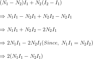
Hence, total weight of copper in the winding of auto transformer proportional to,


In similar way it can be proved, the weight of copper in two winding transformer is proportional to,


N1I1+N2I2
=2N1I1(Since, in a transformer N1I1=N2I2)

Let's assume, Wa and Wtw are weight of copper in auto transformer and two winding transformer respectively,


∴ Saving of copper in auto transformer compared to two winding transformer,
∴ Wtw -Wa=kWtw 
Share:

Recent Posts

Unordered List

Definition List